Why Antenna Installation Angle Matters More Than Most Drone Operators Realize
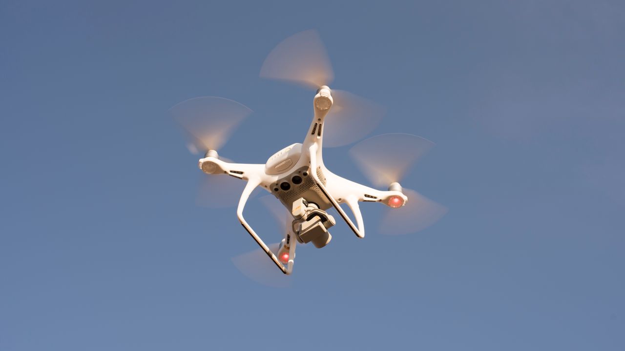
A drone communication link that works well on the bench, works well during pre-flight checks at ground level, and then becomes unreliable the moment the aircraft climbs to altitude has an antenna geometry problem. The signal isn’t weaker because the drone went higher — it’s weaker because the relationship between the antenna’s orientation and the direction of the aircraft changed in a way that moved the link into a part of the antenna’s radiation pattern where gain is low or where a null exists. Understanding how antenna orientation creates signal dead zones, and how installation choices prevent them, is fundamental to building a reliable link.
How an omnidirectional antenna actually radiates
The term omnidirectional is often interpreted as meaning the antenna radiates equally in all directions. It doesn’t. A typical omnidirectional antenna — a dipole or its derivatives — radiates in a pattern that resembles a toroid, or donut shape, centered on the antenna’s axis. Gain is highest in the plane perpendicular to the antenna element, and there are deep nulls directly off both ends of the element, along the axis.
For a vertically mounted antenna on the ground station, the high-gain plane is horizontal — which is exactly where a drone flying level at distance sits. The nulls are directly above and directly below the antenna. This is why a ground station antenna mounted pointing straight up works well when the drone is at a distance but loses signal quality when the drone flies directly overhead at close range: the aircraft has moved into the axial null.
The same geometry operates in reverse on the aircraft. An antenna mounted vertically on the drone has nulls pointing straight up and straight down. When the drone banks into a sharp turn, the antenna tilts with it — and during the turn, one null sweeps through the direction of the ground station. The brief signal dropout that occurs during aggressive maneuvers is often this effect, not interference or range limitation.
The installation angle problem in practice
For fixed-wing drone platforms, the fuselage typically provides a stable mounting surface that keeps the antenna in a consistent orientation relative to the aircraft’s flight path. For multirotor platforms, the dynamics are more complex. During forward flight, the entire aircraft pitches forward — angles of 15–30 degrees are common at cruise speed — which tilts every vertically mounted antenna forward by the same amount.
A 15-degree tilt of a vertical antenna shifts the null from directly overhead to 15 degrees ahead of directly overhead. For a drone flying away from the operator, this means the null is angled slightly toward the ground, which changes the geometry only modestly. For a drone flying toward the operator at speed, the pitch direction reverses, and the null tilts backward — which can point it directly at the ground station if the aircraft is at a steep enough approach angle.
This is not a theoretical concern. It’s a consistent failure mode in FPV racing and long-range cruising applications, where aggressive flight profiles create antenna null encounters that wouldn’t occur during stable level flight.
How mounting position on the airframe compounds the angle effect
Where an antenna is mounted on the drone affects both its orientation during flight and the degree to which the airframe itself blocks part of the radiation pattern. An antenna mounted on the underside of the fuselage, pointing downward, radiates primarily toward the ground — which is the wrong direction for maintaining a link with a ground station unless the drone is flying very high. The same antenna mounted on top of the fuselage, pointing upward, has its high-gain plane closer to horizontal and its null pointing away from the ground.
Carbon fiber airframe elements are particularly problematic because carbon fiber is conductive and absorbs RF energy. An antenna mounted immediately adjacent to a carbon fiber arm has part of its pattern absorbed by the arm material, which creates directional asymmetry in the actual radiation pattern that doesn’t match the datasheet specification for the antenna in free space. Plastic mounting standoffs that position the antenna away from conductive structures restore most of the free-space pattern.
For Drone Communication Antennas on multirotor platforms, mounting locations that keep the antenna element clear of the propeller plane — typically below the main body on a short standoff, or above the body on a riser — give the most consistent radiation pattern across the aircraft’s attitude range during normal flight.
Diversity receivers and how they address the null problem
The engineering solution that most FPV and long-range drone systems use to manage antenna nulls is spatial diversity — using two antennas at different orientations and switching to whichever has the stronger signal at any given moment. A common configuration is one vertical antenna and one horizontal antenna, which covers the null directions of each with the high-gain plane of the other.
Diversity works well when the two antennas are genuinely independent — meaning the null of one doesn’t coincide with the null of the other for the same aircraft position. A vertical and a horizontal antenna mounted on the same mast at the ground station provides diversity in polarization and radiation pattern. Two vertical antennas mounted side by side provide spatial diversity but no pattern diversity — they have nulls in the same directions and switching between them doesn’t help when the aircraft is in a null.
The receiver’s switching algorithm also matters. Fast switching — reacting to signal strength changes on the order of milliseconds — prevents the receiver from staying on a degraded signal while a better one is available. Slower switching can allow a momentary null encounter to persist long enough to cause a video dropout or a lost control frame.
What to check before a flight
The most reliable way to identify antenna geometry problems before they occur in the field is to walk the aircraft through the attitude range it will experience in flight while monitoring received signal strength at the ground station. Pitch the aircraft forward to the cruise attitude, bank it through a full turn at cruise pitch, and note whether signal strength changes correlate with specific aircraft attitudes.
If a consistent signal reduction appears at a particular combination of aircraft position and attitude, that combination represents a geometry where the null is approaching the ground station direction. The fix is to adjust the antenna mounting — height, orientation, or position — until the null is rotated away from the typical flight envelope, or to add a diversity antenna that covers the direction the null was pointing.
This process takes ten minutes on the ground and prevents the kind of in-flight link failure that is easy to attribute to range or interference but is actually a geometry problem that could have been found and corrected before takeoff.